
Steel Mineral Railway Wagons
BR Standard Designs and Later Conversions
Scale Drawings for Models
This page describes the scale drawings I have available for you to produce models of all-metal railway wagons that were used to carry minerals such as coal for the commercial customers of the railway companies. This page covers those wagons with the traditional rectangular body shape with the smaller 16T capcity; similar wagons with wooden bodies, larger steel wagons, and hopper wagons, will be covered by separate pages. The wagons on this page were ordered by British Railways as developments of the Ministry of Transport post-war designs. Also included here are the later updates and conversions that completed the life of the 16T mineral wagon type. Similar wagons for other periods are covered by separate pages.
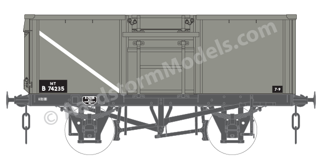
Diagram 1/108 wagon,
British Railways livery.
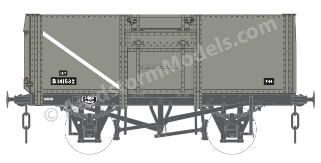
Diagram 1/109 wagon,
British Railways livery.
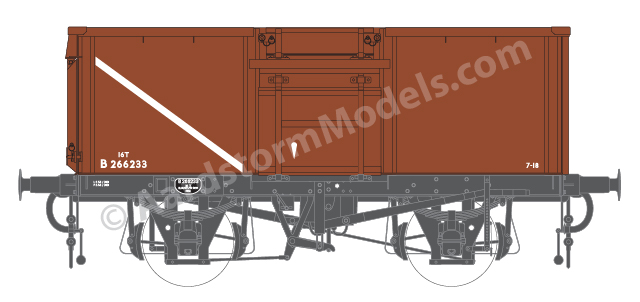
Diagram 1/108 VB8 wagon,
British Railways livery.
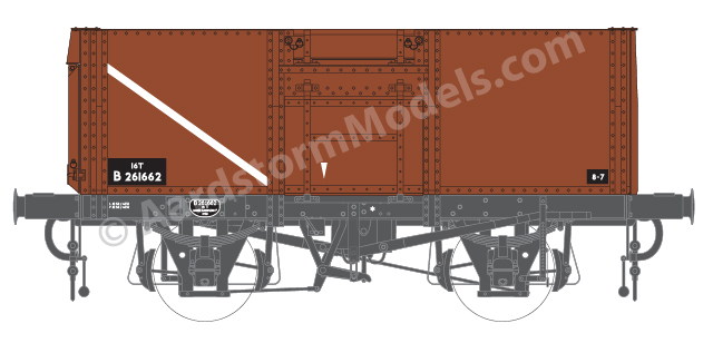
Diagram 1/109 VB8 wagon,
British Railways livery.
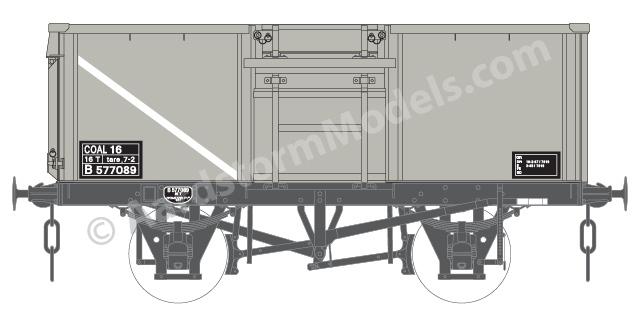
Diagram 1/108 wagon,
British Rail livery.
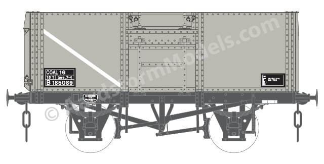
Diagram 1/109 wagon,
British Rail livery.
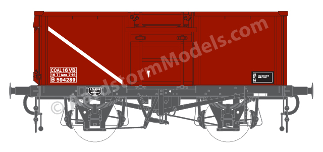
Diagram 1/108 VB8 wagon,
British Rail livery.
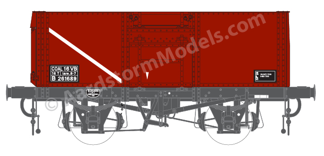
Diagram 1/109 VB8 wagon,
British Rail livery.
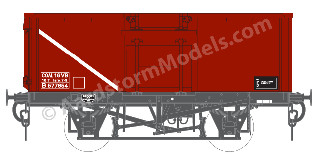
Diagram 1/108 VB4 wagon,
British Rail livery.

Diagram 1/108 R wagon,
British Rail TOPS livery.

Diagram 1/108 RVB8 wagon,
British Rail TOPS livery.
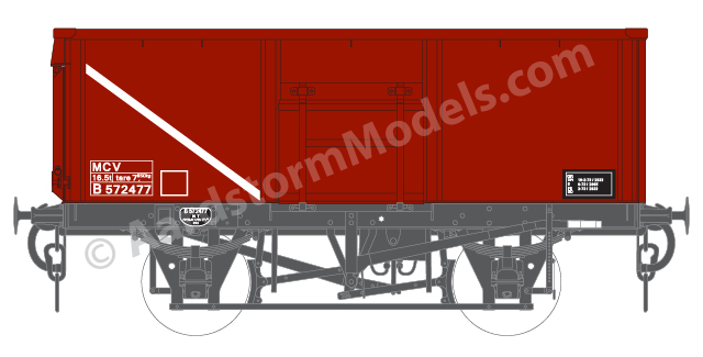
Diagram 1/108 RVB4 wagon,
British Rail TOPS livery.
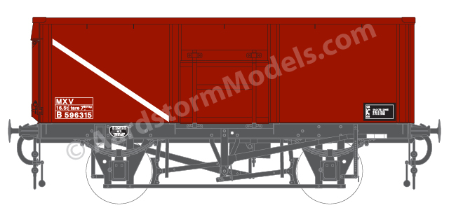
Diagram 1/108 PVB4 wagon,
British Rail TOPS livery.
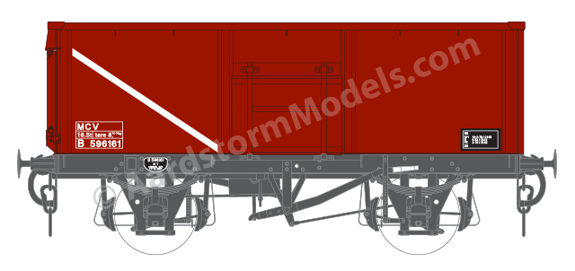
Diagram 1/108 PVB8a wagon,
British Rail TOPS livery.

Diagram 1/108 PVB8b wagon,
British Rail TOPS livery.
Note: Clicking on any of the images on this page, such as those above, will cause a larger version of the image to appear in a new tab or window of your browser (depending on how your browser is set up).
The Drawings
As with all of my standard drawings, each drawing is available in a range of scales, from 2mm:1ft (N gauge) to 16mm:1ft, and most common scales in between. Once you have bought a particular drawing, you will be able to download versions of it in any or all of the available scales. At extra cost I can also provide copies of drawings at a specific scale printed onto A3 or A4 paper and sent to you by post.
The drawings will be provided as multi-page PDF files, one file for each scale. The first page in the file contains the full drawing, arranged for on-screen viewing. The remaining pages each contain a portion of the full drawing formatted for printing out on A4 or A3 paper. A drawing will consist of a number of views each showing an aspect of the wagon, such as a side, end or plan view. Where a view at a particular scale is too large to fit on A4 paper, overlapping pages are provided for you to join together after printing. Alternative pages are also provided for printing onto A3 paper.
To help with this, alignment guides are provided. These take the form of simple fine-lined crosses positioned on either side of the drawing view where I suggest a join be made – typically at a position where a minimum of fine drawing detail crossed the joint. Select one of the overlapping pages and cut it through the drawing along the guides. Carefully position the cut edge on top of the other page such that the crosses are reformed acros the joint. When you're happy with the alignment, tack the pages together with small pieces of transparent sticky tape (e.g. in the vicinity of the guides). Then use a long piece of sticky tape along the whole joint to properly join the pages together. Turn the joined pages over and add a further length of tape on the back.
For the drawings in the smaller scales (4mm and smaller), I've imposed a minimum line width (of around 0.1mm) so that the drawing remains printable. This unfortunately means that fine details amy become obscured or illegible. I suggest that you use a larger scale drawing to examine the details, and use a drawing at the scale you're working to easily transfer dimensions, or even cut up to use as templates.
The drawings for the wagons listed on this page typically contain a side view, a view of each end, additional side views of the underframe where the sides differ, longitudinal and transverse cross-section views to show the interior of the wagon, and plan views of the wagon from above, as a cross-section around half-way down the body, and a plan view of the underframe on its own. Minor variations, such as axleboxes or buffers, are documented by appropriate detail views. There are also often partial views of specific details that are obscured by other features in the standard views.
As well as these views showing the construction of the wagon, I also provide drawings of the wagon in each of the major livery styles it received during its lifetime. The illustrations to the right are a selection of these livery drawings, reduced in size for on-screen viewing. The illustrations below, alongside side each available wagon type, are also selected views from the corresponding drawings, again reduced in size for on-screen viewing.
To produce these drawings, where possible I've started with an official general arrangement (GA) drawing, if not of the wagon type being drawn, then of a very similar type. From there I incorporate details from other drawings and photographs to produce a fully detailed drawing. Source drawings are often distorted or illegible in places, so unfortunately I can't claim 100% accuracy for my drawings. They should however be very close, and models built to them should look the part and require detailed examination and expert knowledge to detect any errors. A brief description of its origins are included on each drawing, so you can assess the likely accuracy for yourself.
How To Order
A single drawing costs £7.50. Additional drawings ordered at the same time cost £5.00 each. Ordering all drawings on this page as a group will cost £20.00.
Click on the buttons below to add the drawings you want to purchase to your basket. Once you have completed your payment, be sure to return to this site to receive a set of access codes for your purchases – one for each drawing and/or one for the group. These will also be sent to you by e-mail.
Enter these codes on the drawings download page here to be presented with links that you can use to view the drawing files you have purchased, and/or download them to your computer. To make downloading drawings for several scales easier, a combined "ZIP" file is also provided that contains all of the scale files for a particular drawing. Most file viewing apps (Explorer on Windows, or Finder on Mac) provide facilities for unpacking the ZIP file to access the individual files.
To order copies of these drawings printed onto paper, please first purchase the downloadable versions, as above. Then please contact me to request a quote for the printed versions, specifiying which scale(s) you want printed, and whether on A4 or A3 paper. The basic price is £1.00 per sheet of A4, or £1.50 per sheet of A3, plus postage which will also depend on the number and size of sheets required. For these drawings, the smaller scales can be fully printed on a single sheet of A4, while the largest scales can need over 20 sheets. A few sheets of A4 can be folded to fit in a C5 envelope to qualify for the normal letter postage rate. Many sheets of A4 are likely to make a C5 envelope too thick for this and require the large letter rate, so may as well be sent unfolded in a C4 envelope. A3 sheets will always be folded to fit either a C4 or C5 envelope. If you need only a few sheets of A4 and would prefer them to be sent unfolded, please specify this when you request the quote.
Copyright
My drawings are subject to copyright, and are licensed for your personal use only. You are not permitted to modify the files in any way, nor supply copies of them to anyone else, other than to get them printed by a third party. The only exception to this is where you are buying the drawings for a small group of modellers (such as a model railway club) working on a single project.
History
Production of the wagon designs ordered by the Ministry of Transport continued into the post-nationalisation period for several years. From around 1950 it was decided that bottom doors for mineral wagons were no longer required, and new designs were issued without them, to diagrams 1/108 and 1/109 for welded and riveted bodies respectively. The absence of bottom doors meant that the braking arrangements could also be simplified, with brake shoes on one side only, operated by both brake levers (usually by means of a Morton clutch). Previously, the earlier wagon designs had brake shoes on both sides of the wagon but the levers only operated the brakes on the same side of the wagon, there being no connecting bar under the wagon that would foul the bottom doors. Many earlier wagons later had their bottom doors sealed shut, althouhgh their brakes remained the same.
These diagrams became the basis for all subsequent BR production of smaller mineral wagons, with some variations and evolution, as diagrams 1/111, 1/114, 1/116 and 1/117. From mid-1955 the later batches of wagons to diagram 1/108, and those to the almost identical diagram 1/117, were delivered with a mix of braking systems: some were fitted with 8-shoe lift-link vacuum brakes; some were prepared for later vb fitting with the 8-shoe brakes, longer buffers and screw couplings, but no hoses or cylinders; others were not vacuum fitted all, using the standard 2-shoe Morton brakes. A few diagram 1/109 wagons were also completed with 8-shoe vacuum brakes. Problems with the unloading arrangements at Goole and the early vacuum brake systems meant that those wagons prepared for vacuum fitting were not so fitted later. The partially fitted versions are covered by my drawings for the fully fitted ones – just leave off the components missing from the prototype.
The 8-shoe vacuum system included a manual changeover lever, the position of which was identified by downward-pointing arrows on the body of the wagons. There are two explanations for the purpose of this lever: to disable the operation of the vacuum system to allow the wagons to be used in unfitted trains; or to modify the braking force of the vacuum system according to whether the wagon was empty or loaded.
There was also a batch of wagons built to a new diagram, 1/106, by BR Derby, just after they completed the D2134 wagons. As the first new design ordered by British Railways rather than the MoT, I've included it in this section, as well as with the MoT designs. It is not clear how these wagons differed from the then standard 1/104 design. They were built with fabricated doors from new, so maybe that was the justification for the new diagram number. Or they may have copied the LMS D2134 design, which is very similar, but not identical, to diagram 1/104, also with fabricated rather than pressed doors. For the 1/106 drawing listed below, I've assumed a 1/104 design with fabricated doors.
Diagrams 1/108 and 1/109 were the standard designs. It is not clear how diagrams 1/111 and 1/114 differed from the standard, and I do not have any information to be able to produce drawings of them. If anyone has authoritative information for this, please let me know and I'll gladly produce drawings to complete the series. Both of these diagrams were first produced by BR Derby, with the first 1/111 wagons following on from the first 1/106 wagons, so they could have been developments of the 1/106 design in the same way as 1/108 and 1/109 were developments of 1/104 and 1/105. Perhaps they acted as protypes for the 1/108 or 1/109 standard designs, as they were first produced about the same time as the first 1/108 and 1/109 were produced by independent manufacturers.
Diagram 1/116 was an experimental version of 1/109 using aluminium sheeting for the body rather the the usual steel. I've assumed they were visually identical to the standard 1/109 design, so I've included them with the 1/109 drawings rather than produce separate drawings.
It is also not clear how diagram 1/117 differed from 1/108. The information I have suggests that they were visually identical to the 1/108 standard, including with partially and fully fitted versions, so I've again included them with the relevant 1/108 drawings.
From about 1966, a large number of unfitted 1/108 and 1/117 wagons were converted to vacuum brakes, using a 4-shoe system with Morton lever. No 1/109 wagons were included in the conversion programme. These wagons also did not have the manual changover lever of the earlier 8-shoe system, so were probably fitted with the Self Adjusting Brake (SAB) system introduced a few years earlier on the larger 21T wagons.
In 1969-76 many unfitted diagram 1/108 wagons were fitted with new welded bodies, the same as the original diagram 1/108 design but without the top flap doors. In 1974-79 many fitted 1/108 wagons were similarly rebodied, along with a few fitted 1/109 wagons, which effectively became diagram 1/108 wagons. This conversion programme included some of the earlier 1966 vb converted wagons.
In 1975-8 a number of former Palbrick wagons were converted to mineral wagons by fitting new bodies (to the same design as the other rebodied minerals) to their 10ft wheelbase underframes (the standard mineral wagons had a 9ft wheelbase). The body design appears to have been stretched to fit the longer chassis, although the rated capacity was 16T, the same as the standard 1/108 wagons, presumably limited by the chassis design. The resulting wagons had a mix of braking systems, buffers and axleboxes inherited from their donor wagons.
The "standard" 1/108 and 1/109 diagrams thus covered a number of significant variations. I have therefore devised a system of suffixes to distinguish the major variations:
- No suffix – The original 1/108 and 1/109 designs.
- VB8 – The original 1/108 and 1/109 designs fitted with the 8-shoe lift-link vacuum brake system from new.
- VB4 – The 1/108 wagons later fitted with the 4-shoe Morton vacuum brake system.
- R, RVB4, RVB8 – The rebodied versions of the 1/108 and 1/109 designs.
- PVB8a, PVB8b, PVB4 – The Palbrick conversions with LMS 8-shoe, lift-link 8-shoe, and 4-shoe Morton vacuum brake systems, respectively.
Liveries
When first delivered these wagons all received the then standard shade of BR grey, or bauxite for the fully fitted versions, both with Gill Sans lettering. The precise shades of these colours varied over the years, the grey in particular becoming progressively lighter. Brief details of fleet numbers are included in each drawing.
After the introduction of the new British Rail blue image in 1964, the colours used became Rail Grey or Freight Brown (similar to bauxite). The lettering style also changed, with most lettering being moved to a 3-line box with white border towards the lower left corner of the body side. These mineral wagons also now displayed their code name of "COAL 16" or "COAL 16 VB". Maintenance information also became more extensive, moving from the solebar to a dedicated box towards the lower right corner. Many wagons received this box without being fully repainted, resulting in a mix of styles.
Following the introduction of the TOPS system 1972, the code names changed to MCO or MCV, and Freight Brown became the standard colour even for unfitted wagons. From around 1982, wagons with the 4-shoe vacuum brake systems were given the new code MXV, so that those with the 8-shoe systems (and the old MCV code) could be more easily prevented from being loaded to Goole. where their brake systems caused problems with the unloading facilities.
Wagon Types

BR design, BR diagram 1/106
16T, rectangular welded body, fabricated side and end doors, with bottom doors and top flap side doors.
Produced 1950–1, by BR Derby.

BR standard design, BR diagram 1/108
16T, rectangular welded body, fabricated or pressed side and end doors, with top flap side doors but no bottom doors. Includes equivalent diagram 1/117 wagons.
Produced 1951–9, by numerous manufacturers.

BR standard design, BR diagram 1/109
16T, rectangular riveted body, fabricated or pressed side and end doors, with top flap side doors but no bottom doors. Includes equivalent diagram 1/116 wagons.
Produced 1950–9, by numerous manufacturers.

BR standard design, BR diagram 1/108 VB8
16T, rectangular welded body, fabricated or pressed side and end doors, with top flap side doors but no bottom doors. With 8-shoe lift-link vacuum brakes, some partially fitted. Includes equivalent diagram 1/117 wagons.
Produced 1957–8, by various manufacturers.

BR standard design, BR diagram 1/109 VB8
16T, rectangular riveted body, fabricated or pressed side and end doors, with top flap side doors but no bottom doors.
Produced 1958–9, by various manufacturers.

BR standard design, BR diagram 1/108 VB4
16T, rectangular welded body, fabricated or pressed side and end doors, with top flap side doors but no bottom doors. Retrofitted with 4-shoe Morton vacuum brakes.
Originally produced 1951–9, by numerous manufacturers. Converted 1966–9.

Rebodied BR standard design, BR diagram 1/108 R
16T, replacement rectangular welded body with fabricated side and end doors, no top flap or bottom doors.
Originally produced 1951–9, by numerous manufacturers. Rebodied 1969–76

Rebodied BR standard design, BR diagram 1/108 RVB8
16T, replacement rectangular welded body with fabricated side and end doors, no top flap or bottom doors. With 8-shoe lift-link vacuum brakes. Some diagram 1/109 VB8 wagons also included.
Originally produced 1957–8, by various manufacturers. Rebodied 1974–9

Rebodied BR standard design, BR diagram 1/108 RVB4
16T, replacement rectangular welded body with fabricated side and end doors, no top flap or bottom doors. Previously retrofitted with 4-shoe Morton vacuum brakes.
Originally produced 1951–9, by numerous manufacturers. Vacuum fitted 1966–9, rebodied 1974–9.

Rebodied BR standard design on Palbrick chassis, BR diagram 1/108 PVB4
16T, replacement rectangular welded body with fabricated side and end doors, no top flap or bottom doors. Body design stretched to fit longer chassis. Original 4-shoe Morton vacuum brakes.
Converted 1975–8.

Rebodied BR standard design on Palbrick chassis, BR diagram 1/108 PVB8a
16T, replacement rectangular welded body with fabricated side and end doors, no top flap or bottom doors. Body design stretched to fit longer chassis. Original LMS 8-shoe Morton vacuum brakes.
Converted 1975–8.

Rebodied BR standard design on Palbrick chassis, BR diagram 1/108 PVB8b
16T, replacement rectangular welded body with fabricated side and end doors, no top flap or bottom doors. Body design stretched to fit longer chassis. Original 8-shoe lift-link vacuum brakes. Most with roller bearings.
Converted 1975–8.
All Drawings Group
To add all of the above drawings (including those not yet available, and any added later) to your basket as a group, at a discounted price of £20:
Clicking on an image above will open a larger view in a separate browser window/tab.
Clicking on the "Add To Basket" buttons will add that set of drawings to your basket.